Support reactions
Find the support reactions and member forces of a simple truss, step by step, and watch them balance in an interactive demo
Last updated 2026-09-25
A truss stays put because every force on it is balanced: the load pushes down, the supports push back, and at every joint the members push or pull until the sum is zero. Three equations, ΣFx = 0, ΣFy = 0 and ΣM = 0, give you the support reactions (Σ just means "add up all the"). The same idea, applied joint by joint, gives you every member force.
Drag the top node
Load
Compression
Tension
The example: a 3-4-5 triangle
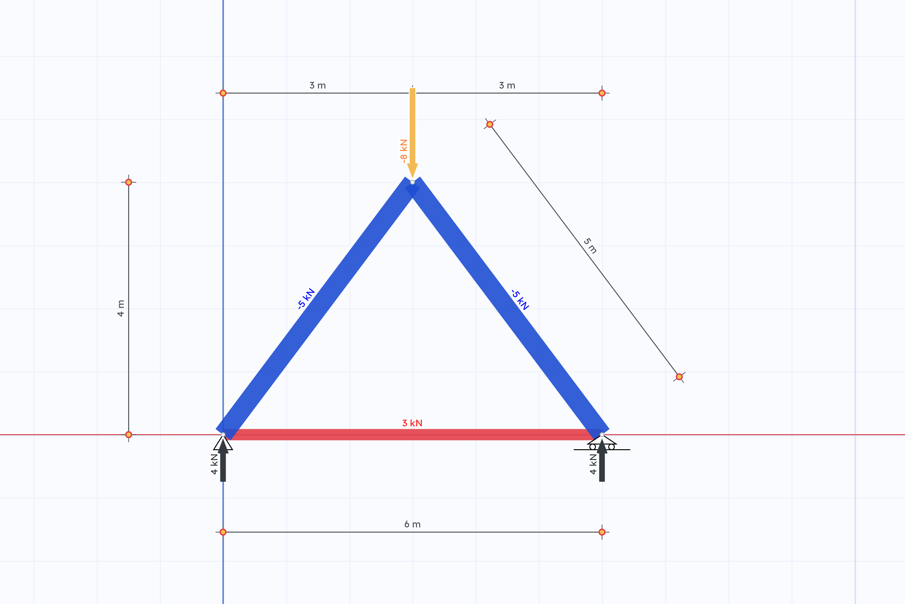
Two members lean in from the supports and meet at the top. A third member ties the bottom together.
- Span: 6 m, height: 4 m, so each sloped member is 5 m long (a 3-4-5 triangle on each side).
- Left support: pinned, which holds the node both horizontally and vertically.
- Right support: roller, which holds the node vertically only.
- Load: 8 kN downward at the top node.
Step 1: Replace the supports with forces
Draw the truss on its own, with nothing attached (a free-body diagram). Remove the supports and put in their place the forces they can apply:
- The pin gives two unknowns, RLx and RLy.
- The roller gives one, RRy.
That's three unknowns, and a flat structure that holds its shape gives you exactly three balance equations. When the numbers match, and the supports are placed sensibly (see Truss stability), these three equations are all you need to find the reactions.
Step 2: Moments about the left support
A moment is how hard a force tries to turn something around a point: the force times its distance from that point (its lever arm). It's the same reason a door is easier to push open far from its hinges. A truss that doesn't move doesn't turn either, so all the moments around any point add up to zero.
Pick the point where the most unknowns meet. RLx and RLy both pass through the left support, so their lever arm is zero and they drop out. That leaves two forces: the load, 3 m from the left support, tries to turn the truss one way, and RRy, 6 m away, tries to turn it the other way.
ΣML = 0: 8 kN × 3 m − RRy × 6 m = 0 → RRy = 4 kN
Step 3: Vertical forces
ΣFy = 0: RLy + RRy − 8 kN = 0 → RLy = 4 kN
The load sits exactly in the middle, so the supports share it equally. Drag the top node sideways in the demo and the split changes: the support closer to the load takes more.
Step 4: Horizontal forces
ΣFx = 0: RLx = 0
Nothing pushes sideways, so the pin doesn't have to. It still could, and that's why the pin is there: without it, the truss would roll away the moment someone leaned on it.
Step 5: From reactions to member forces
Now zoom in on one joint. Every force on it must balance too, and there are only two directions to worry about.
At the top node, the 8 kN load is carried by the two sloped members. Each member's force splits along its slope (see force components): for every 5 units along the member, 4 go vertical and 3 go horizontal.
2 × F × 45 = 8 kN → F = 5 kN (compression)
The horizontal parts, 5 × 3/5 = 3 kN from each side, cancel each other.
At the left support, the sloped member pushes down 4 kN and outward 3 kN. The reaction takes the 4 kN. The bottom member takes the 3 kN, pulling inward, so it's in tension.
Pick each node in the demo to see its forces drawn tip to tail. When the node is balanced, the arrows close into a triangle, the force polygon. If it doesn't close, something is missing.
Solving a truss one joint at a time like this is called the method of joints.
Things to try in the demo
- Drag the top node lower. The member forces grow fast, even though the load stays the same.
- Drag it off-centre. The reactions stop being equal; the support closer to the load carries more.
- Double the load. Every force doubles, so the triangles keep their shape.
- Show the math to see the balance equations filled in for the node you picked.
- Press Reset to 3-4-5 to get back to the whole numbers.
Why flat trusses carry big forces
Each sloped member only lifts with its vertical part. With the member at angle θ above horizontal and a load P at the top:
F = (P / 2) / sin θ
At the 3-4-5 shape, sin θ = 0.8 and F = 5 kN. Halve the height and F grows to about 7.2 kN; at a quarter of the height it's over 12 kN. At zero height it has no limit: a flat triangle can't carry a load at its middle node. That's why real trusses are deep, and why roof trusses need a minimum pitch.
Common mistakes
- Forgetting the pin's horizontal reaction. It's zero here, but it's an unknown until you prove it is. Put it in the free-body diagram anyway.
- Taking moments about an unhelpful point. Pick the point where the most unknowns pass through; each one that passes through it drops out of the equation.
- Mixing up sign and direction. Choose one sign convention (up and right positive) and stick to it. A negative result doesn't mean you made a mistake; it means the force points the other way.
- Using the member force instead of its components. A 5 kN sloped member doesn't put 5 kN into the vertical balance. It puts in 5 × 4/5 = 4 kN.
- Assuming the supports always split the load equally. They only do when the load is centred.
Check it in Truzme
Build this triangle yourself in the Getting started guide, or open it directly and change anything you like.
Example
Getting started
The classic first truss — a simple triangle